Component presence and orientation
Define a named component and visible orientation feature for the approved PCB build.
Review the component workflow
Use Case
AI electronics assembly verification checks a defined visible build condition against the correct product variant. United Vision can be evaluated for component presence and orientation, connector seating appearance and printed identifiers using qualified images. Each station needs representative evidence, agreed acceptance criteria and a validated response; electrical and hidden-joint tests remain separate.
Bring visible build checks closer to the assembly step: confirm the defined component, connector feature or printed identifier while the evidence is still in view.
Inspection workflows
Start with a known inspection gap and the station where the evidence is available. United Vision gives plant teams control of the capture, training and update cycle, with supported plant hardware and one factory license for additional use cases. The team still qualifies each decision and its line response.
Define a named component and visible orientation feature for the approved PCB build.
Review the component workflowInspect a defined seating feature, connector position or cable presentation before a cover hides it.
Review the connector workflowCheck the applied identifier and its expected content for the selected electronic module.
Review the identifier workflowInspection workflows · After placement
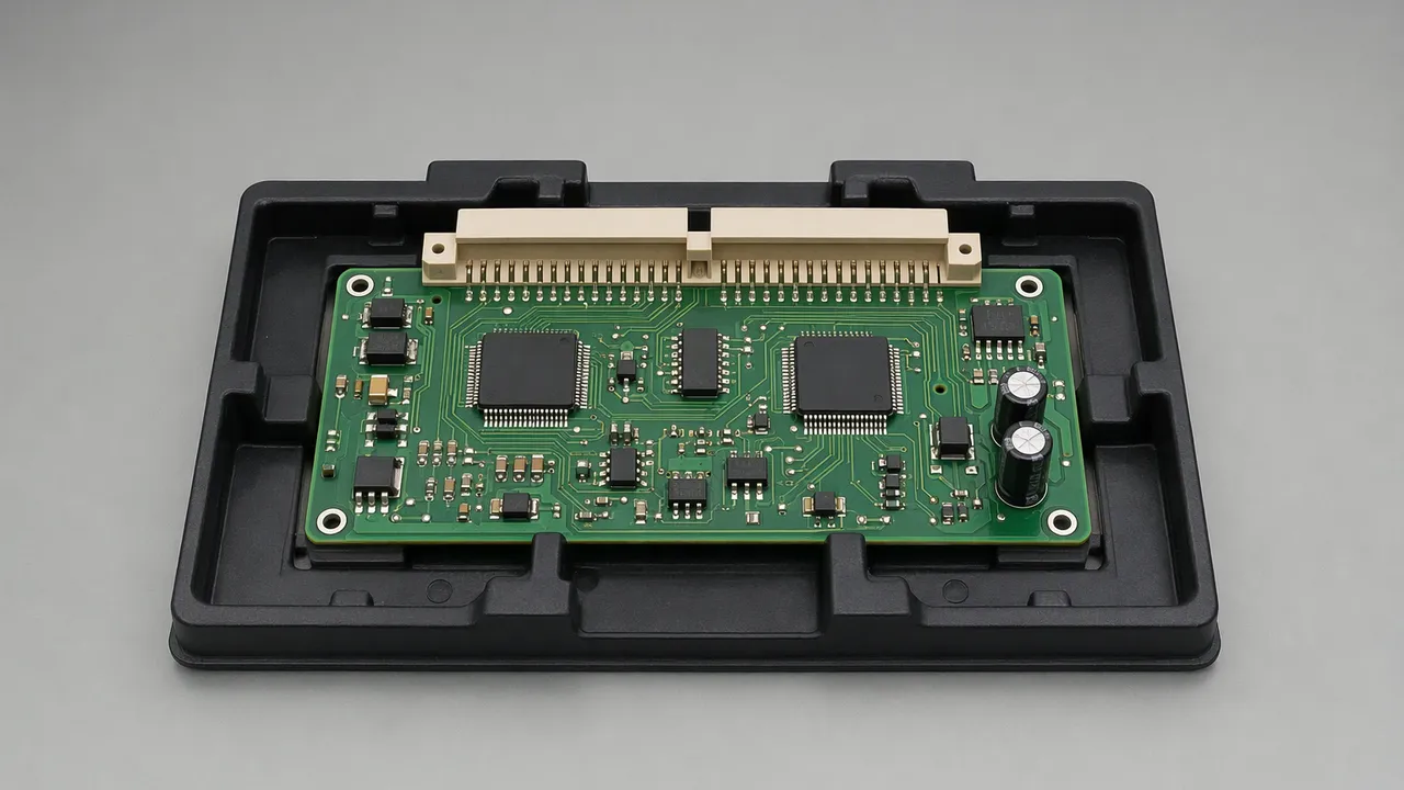
Place the check after the relevant component is installed and before it is hidden. Name the component, region and visible orientation cue that distinguish the approved build from the condition the plant wants to catch.
A component that looks present and oriented correctly has not thereby passed an electrical or hidden solder-joint test. Keep those controls in the separate test plan.
Inspection workflows · After assembly
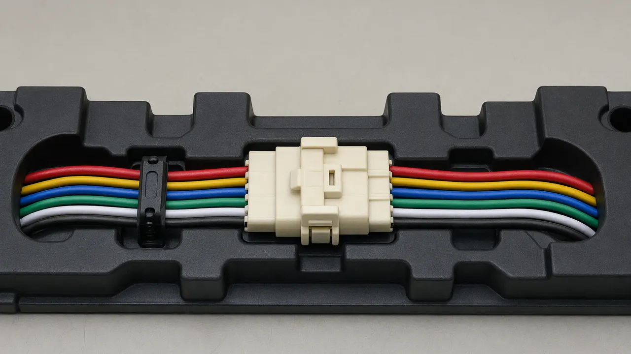
Evaluate the completed connection while its exterior is accessible. Select a visible seating feature, latch position, alignment mark or cable route that has an agreed acceptable condition for that assembly.
Visible seating appearance does not establish internal contact engagement, continuity, insertion force or mechanical retention. Required connection and pull tests remain separate.
Inspection workflows · After labeling
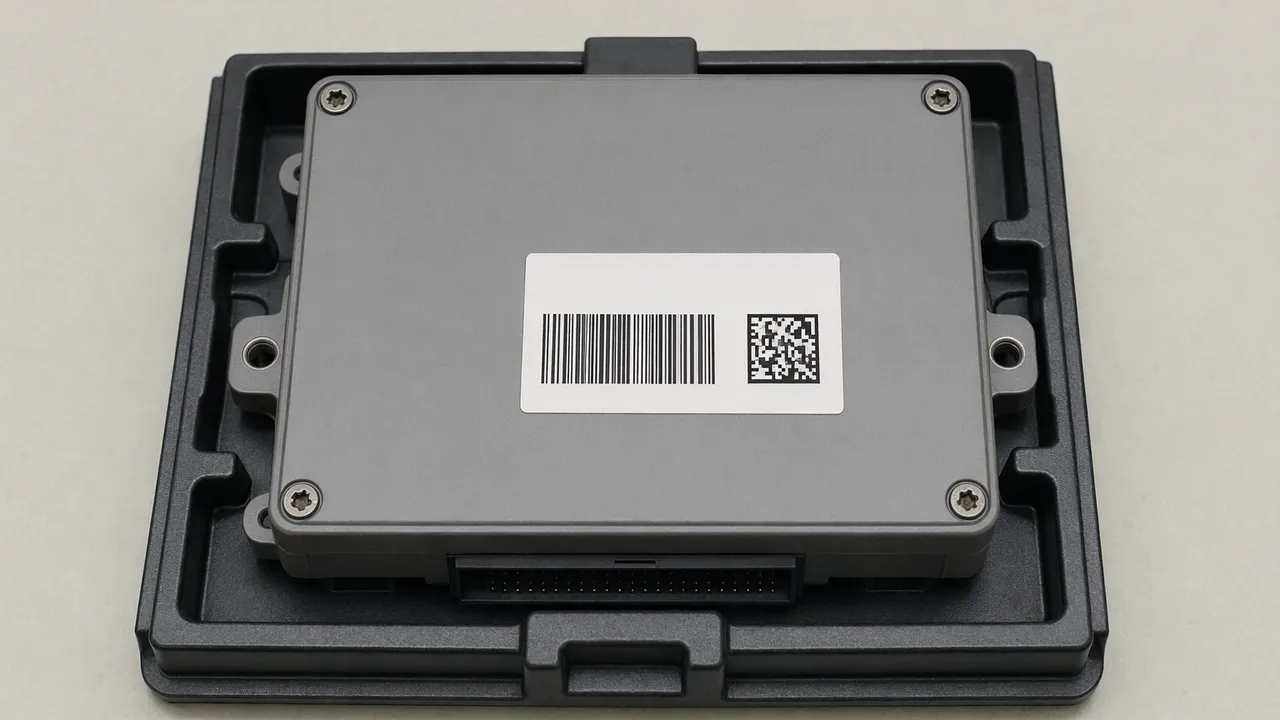
Inspect the module after the identifier is printed or applied. Define required label presence, placement and legible fields, then establish the expected content for the selected product or revision.
Reading an identifier is one part of a traceability workflow. Data matching, retention and downstream use need their own agreed implementation. See the shared label and OCR inspection method for reading and verification boundaries.
Plant-owned lifecycle
Use production knowledge to define a useful visual decision, then test that decision on evidence separate from the training set. Keep acceptance and release responsibility with the plant.
Collect images across revisions, lots, shifts, fixtures and normal presentation changes. Include confirmed target conditions, occluded views and poor images.
Name the feature, correct variant, acceptable variation and exception response. Agree how the selected inspection will follow product changeovers.
Plant experts label relevant conditions and train models in a supported customer-owned cloud account. Configure reading or comparison rules where needed.
Use a separate evaluation set. Record missed conditions, false alerts and uncertain images; test timing, part association and the required plant response.
Deploy the validated inspection to a supported factory-owned edge device. Review new revisions and conditions, then retrain and revalidate before redeployment.
Review the plant-controlled visual inspection platform and camera and edge qualification requirements. Device selection and capacity are scoped for the project. Use the guide to choosing the first AI inspection use case to define the visible signal, evidence and response owner before selecting an assembly station.
Action and ownership
A useful inspection includes the response to an exception and the evidence needed by the person making the release decision.
Define how the correct board or module remains associated with its result through a hold, recapture, rework or review. Test timing, line stops, changeovers and any agreed handling interface.
Name the owner who reviews missing, mismatched or obscured evidence and authorizes release. Agree the evidence to retain and a safe response when an image or inspection result is unavailable.
Buyer questions
It can be evaluated for a named visible component, orientation mark, connector seating feature, cable presentation or printed identifier. The expected condition must be defined for the selected product variant, and representative images must show that acceptable and unacceptable conditions can be distinguished.
No. A visible assembly check does not establish electrical continuity, functional performance, hidden-joint quality or mechanical retention. Required electrical, functional, X-ray, solder-joint and mechanical tests remain separate parts of the plant control plan.
Define the expected component, position, mark and identifier requirements for each approved revision or variant. Include allowed substitutions and optional parts. Validate changeovers and the response when the selected inspection definition does not match the assembly being presented.
A camera can be evaluated for a defined visible seating feature, latch position or alignment mark when the view is clear. The result covers that visual condition only. It does not establish contact continuity, insertion force, internal engagement or pull-out retention.
A match can be considered when the approved expected value, data access and required interface are available. Qualify character or code reading, the matching rule, timing and association between the result and the correct module. Full traceability or a ready-made production-system integration should not be assumed.
Define an exception response for an obstructed, blurred, incomplete or uncertain image. The plant may require recapture, a hold or human review. Validate that the identified assembly stays associated with the result and that an authorized owner controls release.
Production inference runs on a supported factory-owned edge device. Plant teams capture and label images, train models in a supported customer-owned cloud account, validate the inspection and redeploy updates as products and conditions change. Camera suitability, edge capacity and the plant response are qualified for the project.
One recurring factory software license covers unlimited United Vision use cases inside the licensed factory. Hardware, cloud consumption, integration, implementation, support and validation are scoped separately.
Plan the inspection
Bring the product revision, target condition, representative images, station, cycle timing, camera details and current response. This makes image suitability and validation scope concrete.
Map the proposed check to placement, connection, identification and enclosure steps.
Explore electronics inspectionReview image access, decision timing, handling, evidence and the owner of production release.
Review deployment readinessUnderstand the customer-owned images, trained models and customer-specific inspection IP position.
Review data and IP ownershipPrepare a private inspection brief for the first station and record costs that still need to be scoped. One recurring factory software license covers unlimited United Vision use cases inside the licensed factory. Hardware, cloud consumption, integration, implementation, support and validation are scoped separately.
Bring the build definition and the image evidence needed to distinguish the target condition. Agree the validation and response before production use.